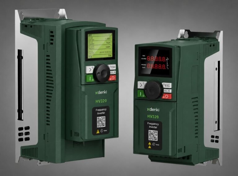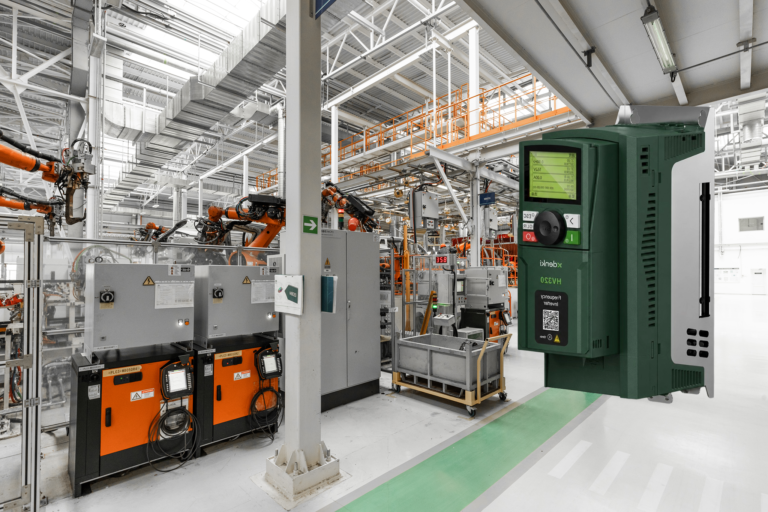
A frequency inverter that trips unexpectedly can bring an entire line to a stop — and the fault display often shows a code rather than a clear explanation. Most inverter faults fall into a small number of recurring categories, and knowing what they typically mean makes troubleshooting far faster than starting from scratch each time.
Start with the Fault Code, Not Guesswork
Every reputable inverter logs a specific fault code when it trips, and that code is the fastest path to a diagnosis. Before checking wiring or swapping components, note the exact code shown on the keypad or HMI and check it against the inverter’s manual — it will point directly to the category of problem, rather than leaving it to guesswork.
Common Fault Categories
1. Overcurrent
Usually caused by a mechanical jam, an undersized inverter for the motor, too-fast acceleration, or a short circuit in the motor cable. Check for mechanical binding first, then verify the acceleration time and inverter sizing against the motor’s actual load.
2. Overvoltage
Often triggered during deceleration, when a motor’s regenerated energy has nowhere to go and pushes the DC bus voltage too high. Extending the deceleration time or adding a braking resistor is the typical fix.
3. Undervoltage
Points to a problem with the incoming power supply — a voltage sag, loose connection, or an undersized supply cable. Check upstream voltage at the source before assuming the inverter itself is at fault.
4. Overheating
Usually caused by blocked ventilation, a failed cooling fan, excessive ambient temperature, or running the drive continuously above its rated load. Check for dust buildup on heatsinks and confirm the enclosure’s ambient temperature is within spec.
5. Ground Fault
Indicates current leaking to ground, often from damaged motor cable insulation or moisture inside the motor. This should be treated as a safety-relevant fault and investigated before restarting — it typically requires a megohmmeter test on the motor and cabling.
6. Motor Overload
Signals that the motor has been drawing more current than its rated value for too long — often due to mechanical overload, a failing bearing, or incorrect motor parameter settings entered in the inverter.
7. Communication Faults
Common in networked systems — usually caused by incorrect baud rate or address settings, a loose or damaged communication cable, or a mismatch between the protocol configured on the inverter and the PLC/SCADA system.
Quick tip: most nuisance trips fall into just two categories — sizing/tuning issues (accel/decel time, current limits) and environmental issues (heat, dust, loose connections). Check these first before assuming a component has failed.
A Practical Troubleshooting Sequence
When a fault occurs, working through a consistent sequence saves time: note the fault code and when it occurred, check for anything that changed recently (load, environment, settings), inspect the physical installation (cables, ventilation, mounting), and only then move to checking or adjusting inverter parameters. Jumping straight to parameter changes without ruling out a physical cause often leads to chasing the wrong problem.
Preventing Problems Before They Start
Most inverter faults are preventable with basic routine maintenance: keeping heatsinks and ventilation paths clear of dust, periodically checking terminal connections for tightness, verifying acceleration/deceleration times still match the current application, and confirming motor parameters after any motor replacement. A few minutes of scheduled inspection consistently prevents far more downtime than reactive troubleshooting after a trip.
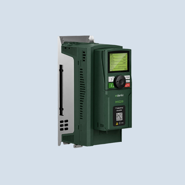
Many of the faults covered in this article are easier to prevent with the right hardware. The XDENKI HV320 Series Frequency Inverter includes intelligent protection mechanisms, comprehensive motor protection, and an independent air duct cooling design that keeps dust away from the circuit board — reducing exactly the kind of overheating and overcurrent issues that cause unplanned downtime.